




サーボポンプ制御CNCプレスブレーキ: Energy Consumption Analysis
By Author: マーク・ハンクス
Energy consumption is an important topic when choosing CNC press brakes. Traditional electro-hydraulic press brakes use servo proportional valves to control upper beam movement, but electro-hydraulic structure losses in this energy competition caused by throttling and overflow reduce overall efficiency.
A servo pump-controlled CNC press brake with variable-speed servo motors can directly control hydraulic flow and pressure according to different bending requirements. This advanced system can reduce unnecessary energy consumption, improve hydraulic efficiency, and provide better temperature stability.
This article will tell the comparation between servo pump and servo valve hydraulic systems through simulation analysis and explain why servo pump technology is becoming a good choice for energy-efficient sheet metal forming.
What Is a Servo Pump-Controlled CNC Press Brake?
A CNC press brake with servo pump technology utilizes an innovative press brake ram movement control system within its hydraulic system. Within this system, a servo motor is responsible for driving the hydraulic pump.
A significant difference between a press brake controlled by a traditional servo proportional valve system and a pump servo system is the method of controlling excessive hydraulic oil flow. The pump servo system alters the hydraulic oil output as per the system's demands for a specific bending cycle, which reduces throttling losses.
As manufacturers become increasingly concerned with the energy demanded by the production processes and the costs of operating a machine, the focus becomes the optimization of the production process. More energy-efficient CNC press brake hydraulic systems will likely be achieved in the near future using smarter control strategies, such as servo pump control technology.
1. How Does a Servo Pump Hydraulic System Work?
The hydraulic schematic of the servo pump-controlled CNC press brake is shown in Figure 1.
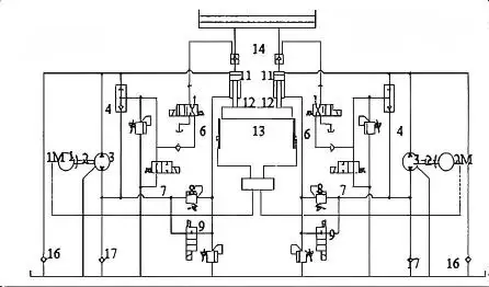
図1. Hydraulic Schematic of a Servo Pump-Controlled CNC Press Brake
The operating process of the servo pump-controlled system consists of five stages:
高速進入ステージ
Servo motors 1M/2M drive the bidirectional fixed-displacement pump (3) in forward rotation, supplying oil to the rodless chamber of hydraulic cylinder (12). 同時に, 給油弁 (11) opens, allowing additional oil from the filling tank to increase cylinder flow. The ram moves downward rapidly, with approach speed controlled by servo motor speed.
作業フィードステージ
When the bending tool contacts the workpiece, the filling valve closes. Hydraulic oil is supplied only by the pump, allowing pressure to build inside the cylinder. The working feed speed is precisely controlled by servo motor rotation speed.
ドウェルステージ
After the ram reaches the bottom dead center, the servo pump stops rotating. The system maintains pressure to reduce springback deformation after bending.
圧力解放段階
現段階では, the pump direction changes under control of the servo motors, and oil is supplied to the rod chamber. The ram moves up slowly under CNC control.
リターンストロークステージ
The servo pump continues to work in the reverse direction. The filling valve is opened to allow the oil in the rodless chamber to return to the filling tank. The return speed is regulated by servo motor speed.
サーボポンプとサーボバルブ油圧システムの比較
| 比較項目 | サーボバルブ制御システム | サーボポンプ制御システム |
| 制御原理 | サーボバルブと比例弁を使って油圧流量と圧力を調整します | サーボモーターで駆動される可変排気量ポンプを使用し、流量を直接制御します |
| 応答速度 | Very fast response (typically 5–50 ms), suitable for high-speed dynamic control | Slower response due to pump inertia (typically 100–500 ms), but sufficient for CNC press brake applications |
| エネルギー効率 | Lower efficiency due to throttling losses and overflow losses; more heat generation | Higher efficiency because hydraulic power is supplied according to actual demand; reduces unnecessary energy consumption |
| 発熱 | Generates more hydraulic heat, often requiring larger cooling systems | 発熱が少なくて済む, improving hydraulic oil temperature stability and reducing cooling requirements |
| 制御精度 | Excellent position, 速度, and pressure control accuracy | 静的精度は高いが、動的追尾性能はやや劣ります |
| システムコスト | Lower component cost, mature technology, easier maintenance | サーボモーターや可変ポンプによる初期投資の増加 |
| システム複雑性 | 標準化されたバルブ部品を備えたより単純な油圧構造 | More complex closed-loop system with servo pumps, control electronics, and additional hydraulic components |
| 過負荷保護 | Fast pressure relief through safety valves, providing sensitive overload protection | Relies mainly on pump power limitation, with slower overload response |
| 騒音レベル | バルブスイッチングのノイズと圧力変動の増加 | よりスムーズな運転と低油圧ノイズ |
As explained in the comparison table above, the main difference between servo pump and servo valve hydraulic systems is the different way to control hydraulic oil flow. A servo pump system controls pump speed according to the required flow rate, which is very helpful in reducing throttling losses and unnecessary energy consumption. On the contrary, servo valve systems regulate hydraulic flow through valve opening and closing, which generates additional hydraulic losses during operation.
バルブ制御システム (Throttling Control)
In a valve-controlled hydraulic system, the pump maintains a constant pressure and flow of oil. A proportional valve allows for complete control of the flow to the hydraulic cylinder.
Under these conditions, the pressure and flow in excess of what is required by the load are disposed of by throttling at the valve or discharged through a relief valve. This converts the excess hydraulic energy to heat and causes energy loss.
Analogy: The water supply is fully open, while the flow is controlled by partially blocking the pipe outlet with a stop valve. The excess water pressure is wasted. These systems almost always use an open hydraulic circuit.
ポンプ制御システム (Volumetric Control)
In a pump-controlled hydraulic system, the movement of the actuators is controlled by adjusting the displacement or speed of a variable-displacement pump, allowing the system to provide the flow and pressure demanded by the load and incur minimal throttling losses.
In this system the output of the pump is exactly the flow needed by the actuator, creating practically no overflow and resulting in almost no throttling and heat losses.
Analogy: A system like this is very similar to a pump controlled water system, variable speed water pump, that does not waste excess pressure. These systems are almost always designed as closed hydraulic circuits, using a variable displacement pump with a fixed displacement motor or hydraulic cylinder.
2. CNCプレスブレーキのエネルギー消費分析
2.1 モデルのセットアップと運用シーケンス
バルブ制御のCNCプレスブレーキ油圧システムのシミュレーションモデルが確立されました。以下に示されています。 図2, and the pump-controlled hydraulic system model of the CNC press brake, as shown in 図3. The operating parameters for both systems are listed in Table 1.
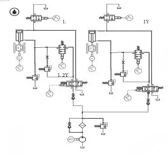
図2 プレスブレーキ用バルブ制御油圧システムのシミュレーションモデル
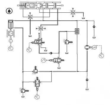
図3. Simulation Model of the Pump-Controlled Hydraulic System for the Press Brake
表1. Action Time and Speed Specifications
| 戦闘 | 高速アプローチ | 動作フィード | 居住 | 圧力解放 | リターンストローク |
| Valve-Controlled Time (s) | 1.5 | 2 | 1.5 | 1.5 | 2 |
| 速度 (mm/s) | 90 | 8.5 | 0 | 0 | 75 |
| Pump-Controlled Time (s) | 0.75 | 2 | 1.5 | 1.5 | 1 |
| 速度 (mm/s) | 180 | 8.5 | 0 | 0 | 150 |
The servo pump-controlled system uses a servo motor to directly regulate pump speed and flow output. Servo motors have advantages over traditional fixed-speed motors with rapid responses and high rotational speeds that ultimately shorten the time of approach and return strokes.
To make a proper assessment, both systems were set with the same hydraulic parameters. The main settings are shown in Table 2.
表2. Key Parameter Settings
| コンポーネント / システム | パラメータ | 価値 |
| Hydraulic Cylinder (両システム) | ボア径 | 170mm |
| ロッド直径 | 160mm | |
| 卒中 | 200mm | |
| バルブ制御システム | ポンプ排水量 | 16cc/回転 |
| モータースピード | 1450回転/分 | |
| ポンプ制御システム | 双方向ポンプ変量 | 16cc/回転 |
| 両システム | 荷重 | 625,000 N (per side) |
| バルブ制御システム | サーボバルブ定格電流 | 40 mA |
| サーボバルブ固有振動数 | 80 Hz |
For the valve-controlled system, servo valve opening was adjusted through input current signals to achieve the required cylinder speeds. Directional and filling valves were controlled according to the operating sequence. The piston displacement-time curve is shown in Figure 4.
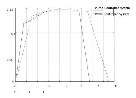
図4. Hydraulic Cylinder Piston Displacement vs. Time Curve
For the pump-controlled system, servo motor speed controlled pump output flow and direction. The filling valve operation was controlled through directional valve switching, and the resulting displacement curve is also presented in Figure 4.
2.2 How Much Energy Can a Servo Pump CNC Press Brake Save?
The servo pump-controlled system reduces cycle time by increasing the speed of the fast approach and return stroke stages. Simulation step size was set to 0.001 s, with total simulation times of 8.5 s for the valve-controlled system and 6.75 s for the pump-controlled system.
Pressure and flow data from the bidirectional pump were exported to MATLAB to calculate power consumption. The power-time curves are shown in Figure 5.
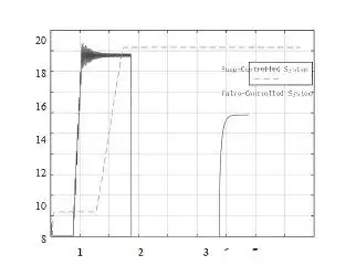
図5. Power vs. Time Curves
During working feed and return stages, the servo pump-controlled system showed higher instantaneous power because energy was directly supplied to the actuator. 対照的に, valve-controlled systems experience additional hydraulic losses caused by throttling and overflow.
MATLAB numerical integration showed that:
• Servo pump-controlled system: approximately 43.69 kJ per cycle
• Valve-controlled system: approximately 124.9 kJ per cycle
そこで, under the same working conditions, the servo pump-controlled system consumed approximately 65% less energy than the valve-controlled system.
2.3 油圧オイル流量の低減と温度向上の利点
The total hydraulic oil flow curves obtained from JS Ragos simulation are shown in Figure 6.
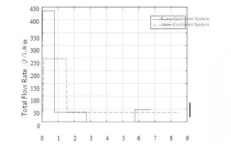
図6. Total Flow Rate vs. Time Curves
Oil volume demand was calculated by integrating the flow rate from the pump outlet and filling valve during the fast approach stage.
From simulation results, we found
• Servo pump-controlled system: ~ 7.53 L
• Valve-controlled system: ~ 10.243 L
During the same operating cycle, the servo pump-controlled system required ~ 26% less hydraulic oil flow volume.
What Type of Customers Are Suitable for Servo Pump-Controlled CNC Press Brakes?
Compared to traditional systems, pump control technology has increased energy efficiency, reduced hydraulic losses, and improved temperature stability. しかし, the use of direct-drive servo motors, variable-displacement pumps, and advanced controls, leads to a higher price compared to traditional systems.
Because of the price, pump control technology is not ideal for every manufacturing environment. しかし, it is especially ideal for these manufacturing environments:
1. High-Volume Manufacturers with Long Operating Hours
In sheet metal manufacturing, energy cost is a large contributor to the overall manufacturing cost when the shop floor operates for long hours.
In traditional servo valve-controlled systems, hydraulic energy gets converted to heat during the process, and this energy loss is a form of throttling loss.
In contrasts to traditional systems, a control system that is based on servo pump technology controls the output of the pump to meet the demand of each bending operation. This system is designed to deliver the required hydraulic energy for each operation to minimize energy consumption during lengthy production.
Pump control technology is ideal for the following industries:
自動車部品製造
大量生産の電気キャビネット
大型家庭用電化器の板金製造
大量金属製造製造
2. Manufacturers Concerned with Increasing Energy Costs
Increasing electricity prices in the industry mean higher operational costs. This situation has forced manufacturers to consider operational costs when purchasing new manufacturing technology.
In this context, pump control technology offers a competitive advantage to manufacturers located in countries with higher electricity costs, or to those manufacturers that want to reduce their carbon footprint.
3. Production Environments Stabilized by Temperature Control of Hydraulic Fluid
Classic hydraulic systems are less efficient because of throttling losses, which generate unnecessary heat. This can lead to considerable negative effects on the hydraulic system during long stretches of high-speed operation.
- Elevated temperatures of hydraulic fluid
- Degradation of hydraulic fluid
- Deterioration of O-rings and seals
- Reduced stability of the system
Servo pump systems, by eliminating energy losses, are designed to generate less heat and operate with greater stability of hydraulic fluid temperatures.
その結果, they are more appropriate for
- Production activities in high-temperature environments
- Continuous operation of bending machinery in 24/7 production facilities
- Production lines requiring high equipment stability
4. Companies Focused on the Value of Their Investment
The purchase price of a pump-controlled system is typically greater than that of a valve-controlled system. しかし, the former is designed to produce important long-term benefits that essentially offset the higher initial cost, 含む:
- Reduction of loss of hydraulic energy
- Decrease in system heating
- Reduction of cooling demand
- Improvement of stability of operating conditions for hydraulic components
These benefits lead to lower overall costs of the system and reduced maintenance over the life of the hydraulic system.
For manufacturers focused on long-term production of their press brakes, pump-controlled technology is a more convenient system.
5. Manufacturing Companies That Are Highly Automated
The requirements of modern automated production lines include:
- Operation of machinery that is highly stable
- A high degree of repeatability
- Production that is extended and, ideally, continuous
Automated production techniques using servo pump control systems of high hydraulic stability are particularly appropriate for the now-typical highly automated production systems that incorporate robotic press brakes and automated bending cells.
サーボポンプ技術の利点
1. Increased Speed
The response time of an asynchronous motor driven by a variable-frequency drive is around 600 ms. 対照的に, with permanent magnet synchronous motors and servo drives, the system is able to achieve a response time of 50 ms.
2. Enhanced Control
With a servo motor pump-control system, a closed-loop control system is implemented. Commanded values are continuously compared with the actual values through speed and pressure sensors.
The control system auto-tunes the servo-motor and pump system for optimal control of pressure, 流れる, and motion.
3. Reduction in Energy Consumption
Since a servo motor pump-control system is designed to be a variable-speed control system, the servo motor is able to adjust its speed to the flow demands of the system. そこで, when the system operates at low speed, the energy consumption of the system reduces.
In different machine configurations and different operational conditions, the energy savings can be between 30% and 80%.
4. Integrated Hydraulic System
A servo motor pump-control system allows a fixed-displacement pump to provide a proportional output. This reduces the requirement for many system components and therefore provides a more simplified system.
The system reduces the continuous high-pressure overflow and lowers the temperature of the hydraulic oil, which extends the service life of the entire hydraulic system.
5. Reduced Noise Level and High Environmental Compatibility
The speed control feature of a servo motor pump-control system means that the noise level of the system is only as high as the current operating demand.
The typical noise level can be around 8-10 dB lower than that of a standard hydraulic system, greatly enhancing the workshop's acoustic environment.
結論
Servo pump-controlled CNC press brakes give a more energy-efficient option compared with traditional servo proportional valve-controlled hydraulic system. By directly controlling pump speed and hydraulic oil flow according to the actual bending requirements, the servo pump technology can reduce throttling losses and improves overall hydraulic oil efficiency.
According to JS RAGOS simulation analysis, the servo pump-controlled system consumed approximately 65% less energy per bending cycle compared with the servo valve-controlled system under the same operating conditions. 他に, the reduced hydraulic flow demand helps decrease heat generation and control hydraulic oil temperature better during continuous machine working.
For sheet metal fabricators with high production volumes, long machine operating hours, and increasing energy trouble, JS Ragos servo pump-controlled press brakes can provide significant long-term benefits.
JS RAGOS is committed to developing energy-saving CNC press brake and intelligent sheet metal forming solutions. By bringing advanced hydraulic technology to practical manufacturing we help customers achieve more efficient and sustainable production.
FAQ
Q1. What is a servo pump-controlled CNC press brake?
Servo pump-controlled CNC press brakes feature with servo motors directly controlling hydraulic pump speed and output flow. Compare with traditional valve-controlled systems, it supplies hydraulic power according to actual bending requirements and save energy.
Q2. How much energy can a servo pump CNC press brake save?
According to JS RAGOS simulation results, the servo pump-controlled system consumed approximately 65% less energy per cycle compared with a servo valve-controlled hydraulic system under same operating conditions.
But the real energy savings are influenced by a lots of factors such as machine configuration, production cycle, 曲げ条件, and operating hours, 等.
Q3. What’s the difference between a servo pump system and a servo valve hydraulic system?
A servo valve system controls hydraulic oil flow by controlling valve opening and closing, which would result in throttling losses and higher heat generation.
A servo pump system controls hydraulic flow by regulating pump speed, allowing hydraulic power to be supplied only when needed. It is more friendly with energy efficiency, and hydraulic oil temperature.
Q4. Are servo pump CNC press brakes suitable for all manufacturers?
Servo pump CNC press brakes are especially suitable for sheet metal fabricators with high production volumes and long operating hours.
For customers with not high machine utilization or who don’t have enough budgets, traditional servo valve-controlled systems could still be a suitable option.
Q5. Can servo pump technology improve CNC press brake performance?
はい. Servo pump systems can improve machine efficiency by providing faster approach and return working speed and more stable operation during continuous production.
Q6. Is a servo pump CNC press brake worthy for higher investment?
Servo pump systems usually are more expensive than servo valve systems, but they can offer better long-term operating costs and return on investment due to their lower energy consumption and heat generation.