


Complex Sheet Metal Part Bending: Reverse Transfer-Based Planning
By Author: マーク・ハンクス
Part bending of complex sheet metal requires the planning of a series of steps to optimize manufacturability, avoid collisions with the tools, and increase process efficiency. It is prevalent in the production of many products in the home, automotive and aerospace industries and even in ship construction and repair. With advanced design and production techniques, such as CAD systems and CNC programmable press brakes, the need to automate the planning of the bending process has become even more critical.
はじめに
When dealing with the bending of complex sheet metal components, most of the work is done by the operator. It is the responsibility of the engineer to manually choose the appropriate tools and design the bending sequence for each component, which is especially burdensome for components with a large number of bends and complex geometries. The methods that are typically used are iterative in nature and very inefficient.
CNC press brake bending sequence optimization is an important topic in improving production efficiency when manufacturing complex sheet metal components.
The introduction of modern CAD/CAM and CNC technologies has led to the development of powerful bending simulation and programming systems, These automated sheet metal bending process planning systems can reduce manual programming time and help fabricators achieve good bending quality.
とか:
• Radan (Planit, 英国): 3D sheet metal process calculation and bending sequence planning
• MBend (Metalix, Israel): bending simulation and process planning for complex 3D parts.
• DA-66S / DA-69S (一部, オランダ): Integrates 3D bending sequence optimization into CNC press brake controllers.
The fundamental task of bending programming is sequence planning. For a component with N bends, the theoretical sequence space reaches N! possibilities. Among these combinations, only some sequences are feasible due to geometric constraints and collision risks.
This article introduces an efficient process planning algorithm based on reverse state transfer. By applying backward reasoning, the algorithm reduces unnecessary bending feasibility tests, eliminates invalid sequences earlier, and obtains all feasible bending sequences with improved computational efficiency.
Why Complex Sheet Metal Bending Requires Advanced Process Planning
Numerous factors impact the bending of sheet metals of high complexity. These include the straightness, the precision of the angles, the plan for the bending process, as well as the selection of the tools, and the level of capability of the equipment and the operators. Even with the use of advanced and precise equipment such as the press brake, poor planning of the process will result in inefficient production and inconsistencies in the bending angle and dimensions.
As such, advanced planning is critical in the production of complex sheet metal components in order to fine-tune and optimize every aspect of the bending process. This includes the calculation of the flat pattern, the bending sequence, the selection of tools, and the configuration of the bending parameters.
1. Dimensional Accuracy
Dimensional accuracy of the bent components is influenced by the bending parameters as well as the precision of the backgauge of the press brake, the accuracy of the sheet metal blank cut, and the precision of the flat pattern.
For the most part, the cutting accuracy of laser cutting and punching machines, as well as the backgauge positioning accuracy of high-end CNC press Brakes, satisfy the majority of production needs. それでも, flat pattern accuracy is neglected during production.
When sheet metal models are unfolded, various methods of calculation, such as the K-factor based on the DIN standard and the two-times-material-thickness method, are employed. These methods primarily address the bending angle, the type of material, and the thickness of the sheet.
それでも, flat-pattern dimensions depend not only on the parameters of the material and the bending process, but also on the bending tools. The same material and thickness can yield different developed dimensions depending on the structures of the tools, the opened gaps of the V-dies, and the bending radii.
Consequently, JS RAGOS has carried out numerous practical bending tests and created an empirical bending database using real production data. This database allows the optimization of flat-pattern calculations, results in more precise developed dimensions, and enhances the manufacturing precision of intricate sheet metal components.
2. Straightness and Angle Consistency
High forming forces during bending result in elastic deformation of the bending machine's worktable and ram. This deflection causes bending angle variations along the bending length, and is especially pronounced at the workpiece's bending mid-point.
To achieve uniform bending angles along the bending length, most press brakes employ a crowning system to address the worktable and ram deflection.
Crowning systems are used to gain angle precision and consistency. If the press brake's overall machine structure is weak, then the system will most likely have to compensate for a lack of precision and consistency to the detriment of straightness of the workpiece.
It is of utmost importance to have a strong press brake structure in the manufacturing of complex components.
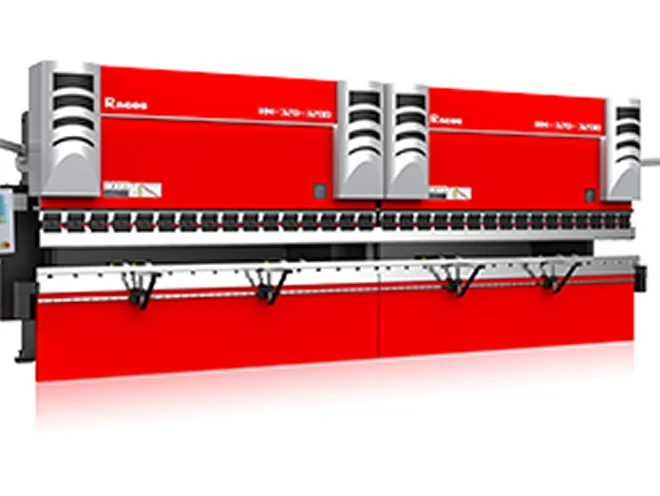
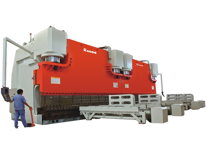
JS RAGOS press brakes incorporate a ram system and worktable system of higher strength and heavy-duty design that enhances the overall machine structure. This leads to the ram and worktable experiencing much less deflection under the same bending load. そこで, a small amount of crowning is able to achieve angle precision and consistency as well as increasing the accuracy along the entire bending length.
3. Tool Selection and Tool Change
The bending of complex sheet metal components is greatly affected by the selection of appropriate tools.
The upper and lower tools must be compatible with the material, シート厚, 曲げ長さ, and geometry of the workpiece. Using incorrect tools can cause bending clashes, angle mistakes, or deformation of the workpiece.
実際の生産において, rapid installation and replacement of tools is beneficial.
The press brake industry has created a variety of tools to accommodate the many different needs of the industry.
CNC Adjustable-Opening Lower Die: This is a system on large press brakes that offers the capability of automatically adjusting the opening of the V-die to the sheet thickness. This system provides greater flexibility in production.
Rotary Dual Tool System: This system offers the ability to quickly change two upper tools, each with different profiles, by a swinging or rotary mechanism.
Segmented Upper Tool System: This system consists of a tool holder that is permanently mounted to the machine, with tool segments that can be selected to have different profiles and different radii. This system improves the efficiency of changeovers by eliminating the replacement of the tool holder.
4.Bending Sequence Planning
The bending sequence is of great importance in the processing of complex sheet metal parts.
Contemporary CNC press brakes have the capability to utilize control systems like the Delem DA66S and DA69, ESA S875, その他, to conduct 3D programming and simulations. Following the importation of the part model, these systems can automatically construct and optimize the bending sequence.
Delem DA53Tx and DA58Tx controls offer 2D programming as well. These advancements significantly decrease the amount of time required for manual programming, and enhances the accuracy, stability and efficiency of the production of parts with a high level of complexity.
Advanced CNC Press Brake Systems for Complex Sheet Metal Components
Conventional press braking systems, along with a certain amount of operator skill and experience, are no longer adequate to satisfy the demands of modern, high-accuracy, high-efficiency production of complex sheet metal components.
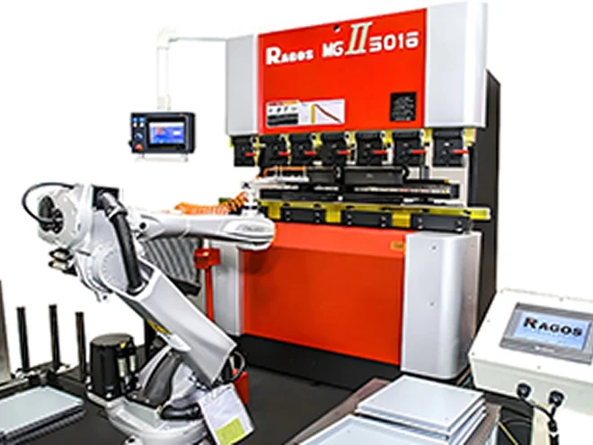
New generation CNC press brakes have the ability to combine advanced controls, 自動化, high-precision hydraulics, and advanced tool and wear component systems. その結果, significant advancements in bending accuracy, 効率, repeatability and stability of the production processes are achieved for complex sheet metal components.
How CNC Press Brakes Improve Complex Sheet Metal Production
Modern requirements for producing complex sheet metal parts demand higher accuracy and efficiency that traditional bending equipment and operator skills cannot provide. Modern CNC (コンピュータ数値制御) press brakes utilize cutting-edge CNC systems and combine hydraulic controls, optimization of tool sets, and various techniques of automation to enhance accuracy, 効率, and overall stability in the production of complex sheet metal components.
1. Advanced CNC Control System Improves Programming Efficiency
When it comes to producing complex bent sheet metal, an advanced CNC system plays an essential role.
High-end CNC press brakes often contain dedicated bending control systems, とか:
- Delem DA66S and DA69S
- ESA S875
- Cybelec CT12 and VP88
These systems provide 2D and 3D graphics in addition to the capability for bending simulations and automatic calculations for bending sequences. These systems allow operators to identify issues that may arise in production, とか:
- The suitability of the bending sequence
- If the part will interfere with the tool
- If the part will obstruct the backgauge
CNC software allows the process to be simulated and optimized, which can greatly minimize the amount of trial bends required. The software provides bending instructions, which help increase programming accuracy and decrease the programming time, thus increasing overall production efficiency for complex sheet metal parts.
2. Proper Tool Selection Reduces Bending Operations
When manufacturing complex parts, choosing the correct bending tools is imperative.
An example of the limitations of using a forming method that involves multiple bending steps in combination with a punch that has an acute angle is if you need to create a workpiece with a curved profile. On top of the difficulties that can arise with maintaining consistent curvature and accuracy of the profile, this method is also very inefficient due to the large number of bending steps required.
If a punch with a radius, such as an R10, R20, or R30 punch, is used, the radius can be created in a more efficient manner due to the large reduction in the number of bending steps required.
For workpieces with intricate profiles, custom made forming tools can be used to achieve the profile in a single bending step, which also significantly reduces the time required to process the workpiece.
In complex sheet metal fabrication, the choice of tool greatly affects not only the precision of bending but overall efficiency of the manufacturing process.
3. Real-Time Angle Measurement and Automatic Angle Compensation
For sheet metal parts with complex geometries, achieving consistency in bending angles during production is problematic because of the unpredictable nature of material behavior and springback.
A CNC press brake that is equipped with a system of real time measurement of the bending angle is able to recognize the angle of bending that has occurred and is able to automatically correct for that bend.
Collision Detection in Automated Sheet Metal Bending
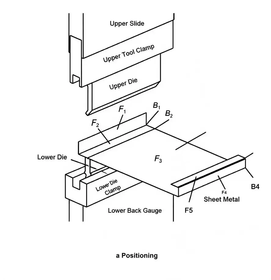
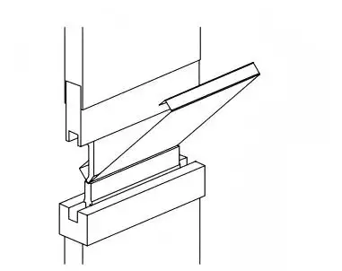
A complex sheet metal bending operation consists of two essential stages: positioning and bending.
During positioning, the workpiece is aligned with the centerline of the lower tooling surface (Figure 1a). 曲げる間に, the upper tooling moves downward and forms the sheet along the bending line to achieve the required angle (Figure 1b).
b Bending
図1: Schematic diagram of the bending process (a) 位置づくり (b) ベンディング
For a four-bend part (B1–B4), the workpiece contains five flat faces (F1–F5). Collision detection must evaluate possible interference between the sheet metal, upper tooling, lower tooling, クランプ, and back gauge during both positioning and bending stages.
Only when a bending operation passes both collision checks can it be considered feasible. そこで, a complete bending sequence is feasible only when every individual bend satisfies the feasibility requirement.
Forward vs Reverse Transfer Method Comparison
Conventional optimization methods, such as genetic algorithms, treat each bending sequence independently within the large N! solution space. This results in repeated calculations and limited reuse of previously obtained information.
The proposed state-based method represents bending operations as transferable process states. Each state records bending feasibility information and provides reference knowledge for subsequent calculations.
State Definitions
For a part with N bending positions:
• N large states (BS): Represent the progressive bending stages.
• N small states (SS): Represent possible bending positions within each stage.
The complete system contains N² states, denoted by
BSiSSj
Where i is the quantitative parameter of the bending stage and j is the parameter of the selected bending position.
Each state retains the results of the collision tests and thus provides a reusable knowledge base.
Transfer Mechanisms
The reverse state transfer mechanism follows three principles:
- Large states transfer information according to the bending sequence.
- Small states within the same large state remain independent.
- Identical small states between adjacent large states do not directly transfer information.
The algorithm retrieves the previous state's feasibility data and combines it with the existing bending position data before calculating a new state. This information constructs an N × N state transfer matrix. In this matrix, the rows are BS states and the columns are SS states.
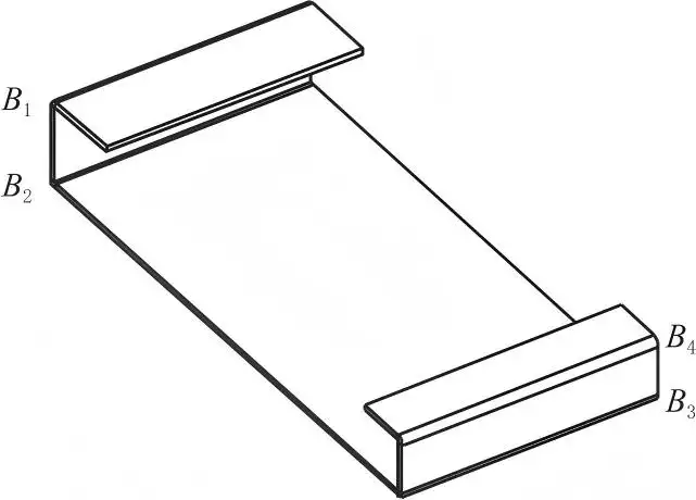
図2: Example part with 4 bends.
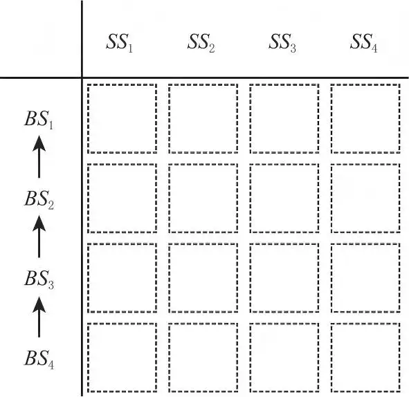
図3: Reverse state transfer matrix (4×4)
例 - Four-Bend Part
To illustrate the reverse state transfer process, a part with four bends is used. Each bending position is numbered as shown in Figure 2, and the corresponding reverse transfer matrix is shown in Figure 3.
Initial Large State (BS₄)
The reverse calculation begins from the final bending stage, BS₄. Since no previous state information exists, every SS position must be independently tested.
Positions BS₄SS₁ and BS₄SS₄ generate collisions with tooling (Figures 4a and 4d), while BS₄SS₂ and BS₄SS₃ pass collision detection (Figures 4b and 4c).
The feasibility data stored in BS₄ becomes:
• BS₄SS₂: {[2]}
• BS₄SS₃: {[3]}
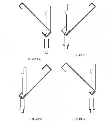
図4: BS₄ bending feasibility tests (a)-(d)
Subsequent Large States
After BS₄ calculation, previous feasibility data is transferred backward to BS₃, BS₂, and BS₁.
For each state BSiSSj, the algorithm:
- Retrieves feasible bending sets from BS(i+1).
- Combines the previous sequence information with the current position.
- Performs collision testing only on necessary candidates.
- Stores validated sequences as new feasibility data.
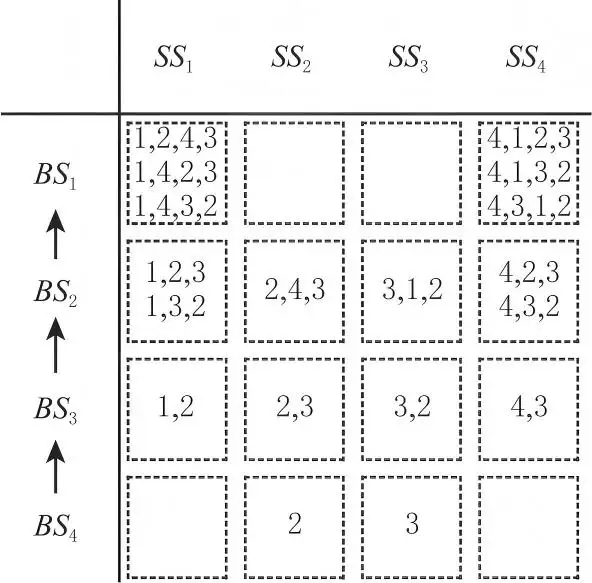
図5: Final reverse state transfer matrix
例えば, BS₃SS₁ obtains the test set:
{[1,2], [1,3]}
The sequence [3,4,1,2] passes collision detection, ただし [2,4,1,3] fails due to interference (Figure 6a and Figure 6b). そこで, BS₃SS₁ stores:
{[1,2]}
同様に:
• BS₃SS₂: {[2,3]}
• BS₃SS₃: {[3,2]}
• BS₃SS₄: {[4,3]}
For BS₂ calculations, duplicate combinations are eliminated to avoid unnecessary tests. The obtained feasibility data includes:
• BS₂SS₁: {[1,2,3], [1,3,2]}
• BS₂SS₂: {[2,4,3]}
• BS₂SS₃: {[3,1,2]}
• BS₂SS₄: {[4,2,3], [4,3,2]}
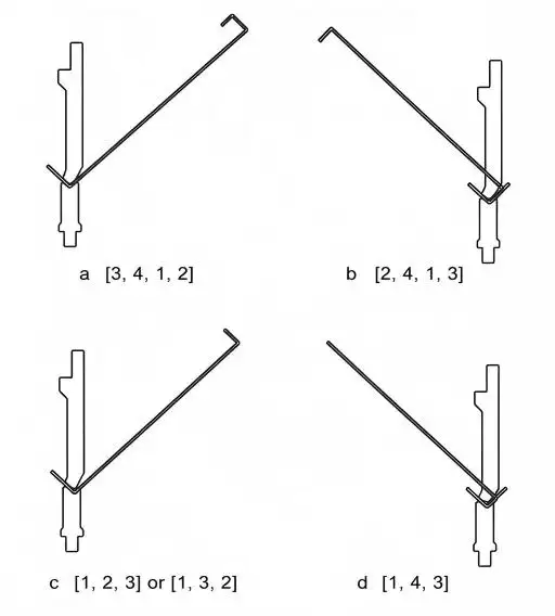
図6: Bending feasibility tests in subsequent BS
State Transfer Direction Selection
Within the state transfer matrix, SS states remain independent because each bending position is processed only once. The transfer direction between BS states is determined by the geometric evolution of sheet metal forming.
In physical manufacturing, sheet metal bending progresses from a flat blank to the final formed component. This process follows a natural forward direction from BS₁ to BSₙ.
しかし, in a software environment, the reverse transformation—from the final formed geometry back to the flat blank—can also be simulated. This enables backward reasoning through reverse state transfer from BSₙ to BS₁.
The efficiency difference between forward and reverse transfer mainly depends on when invalid bending states are eliminated.
表1: Comparison of Forward vs Reverse Transfer Characteristics
| アスペクト | Forward Transfer | Reverse Transfer |
| Starting state | Flat blank | Fully formed part |
| Initial interference level | 低い | 高い |
| Invalid state elimination | Occurs later | Occurs earlier |
| Experience propagation | More invalid states transferred | Invalid states removed quickly |
| Overall test requirement | 高い | 下げる |
State Transfer Direction Comparison
To evaluate the efficiency of different transfer directions, a sheet metal part with eight bends was selected as the test model (Figure 7e).
Table 1 presents the bending feasibility test numbers and pass results at representative states. Figure 8 compares the overall calculation efficiency between forward and reverse transfer methods.
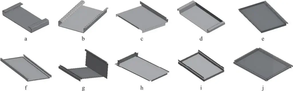
図7: Test part with 8 bends
表2: Key state data comparison between forward and reverse transfer
| State | BS₁ | BS₂ | BS₇ | BS₈ |
| Forward Transfer | テスト: 8 | テスト: 56 | テスト: 2328 | テスト: 1120 |
| Pass: 8 | Pass: 40 | Pass: 1120 | Pass: 540 | |
| Reverse Transfer | テスト: 540 | テスト: 840 | テスト: 28 | テスト: 8 |
| Pass: 540 | Pass: 540 | Pass: 14 | Pass: 4 |
In forward transfer mode, the initial flat blank state contains fewer geometric restrictions. そこで, almost all bending operations pass feasibility testing at the beginning stage. しかし, as the shape becomes more complex, invalid sequences accumulate and continue transferring through later states. At BS₈, a significant number of generated sequences still require rejection.
対照的に, reverse transfer starts from the nearly formed component, where geometric interference is more likely to occur. Invalid bending positions are identified immediately at the initial calculation stage. その結果, fewer infeasible sequences are transferred to subsequent states.
This difference is illustrated in Figure 8. The solid lines display total accumulated feasibility data pre-validation. The confirmed valid bending sequences are represented by the dashed lines. The space between the two curves shows the absence of valid process experiences.
The forward transfer generates a large number of invalid states and demands considerably more collision tests. The reverse transfer avoids invalid states early in the process and generates a smaller set of tests and thus a higher overall planning efficiency.
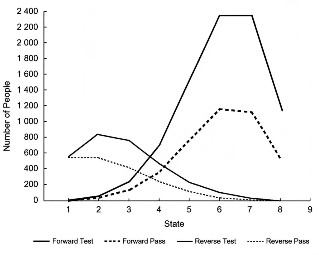
図8: The number of tests in forward and reverse transfer modes
結論
Collision detection for sheet metal part bending requires the sequence of each bending operation to be verified. Each bending operation is verified by checking if a collision occurs with the surrounding environment. The feasibility of each bending operation is determined by checking if the operation can be performed without a collision occurring.
The reverse state transfer algorithm solves this issue by using backward transfer and reasoning to validate the process of different bending states.
The primary benefit of the reverse state transfer algorithm is:
• Decreased expenses: invalid bending sequences and unnecessary calculations for collision detections are removed.
• Complete sequences: the final state enables the determination of all valid bending sequences.
• Knowledge of previous states: the feasibility information of a state is referenced in the calculations of the following states.
• Planning processes of different scope: the matrix-based structure enables components that have different numbers of bending operations.
Testing for collisions and applying reverse state transfer has proven to increase the efficiency and accuracy of planning the bending of complicated sheet metal components. The algorithm offers a solution to the manufacturers for creating a bending sequence that is feasible and allows for additional optimization addressing production, ツール, and the constraints of the manufacturing process.
Are you in search of innovative sheet metal bending methods? The advanced press brakes and bending systems provided by JS RAGOS target improved efficiency, 精度, and reliability in production. Partner with our skilled engineers to develop the best tailored solution for your needs in metalworking.
よくある質問
Q1: What is the importance of planning in bending sequences?
Planning bending sequences helps avoid collisions and unnecessary iteration in production trials. It also boosts accuracy.
Q2: What difficulties are presented with intricate sheet metal bending?
Difficulties with intricate sheet metal bending include large sequence combinations, planning efficiency, and tooling interferences.
Q3: What is the impact of reverse state transfer on bending sequence planning?
Reverse state transfer helps eliminate invalid sequences, resulting in a reduction of unnecessary feasibility testing.
Q4: What is a bending feasibility test?
A bending feasibility test checks if a bending process would lead to a collision of the workpiece, ツール, あるいはその両方.
Q5 How does CNC press brake software optimize bending sequences?
CNC press brake software can optimize bending sequences through analyzing part 3D drawing of workpieces, tooling shapes stored in tooling library and simulating potential collision risks during the bending process. When clients choose press brake configurations, they can consider adopting Advanced CNC systems, such as Delem DA66S, DA69S, DA58TX, ESA S875, and Cybelec CT12/VP88 which support 2D/3D graphic programming, 2D/3D import, bending simulation, and automatic bending sequence calculation.
Before actual production, operators can check potential interference between the workpiece, ツーリング, and back gauge position through 3D simulation to generate the most efficient bending sequence to speed up programming, reduce manual trial bending time, and enhance the production stability and consistency when manufacturing complex sheet metal components.